Sabtu, 13 November 2010

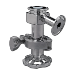
Pneumatic actuator for sanitary falve

Pneumatic Diaphragm Valve
Pneumatic valve
Connection mode:Pneumatic Diaphragm Valve
Specification:1/2"-2", applied to the stainless steel pipeline system
Material quality :SUS316L
Standard :ISO,DIN,IDF,SMS
Application :pharmacy,beer,food,dairy,beverage,cosmetic,chemical industry
Working principle : remote-controlled operation by the driving gear or manual operation by The handel Three drive forms: normally closed, normally opened and opened and closed by two air flues separately
We can offer all kinds of the sanitary vlaves and can manufacture them according to any drawings.

welded butterfly sanitary valve specification

Sanitary Welded butterfly valve
Connection mode:welded
Specification :1"-4", applied to the stainless steel pipeline system
Material quality :SUS304,SUS316L
Standard :ISO,DIN,IDF,SMS
Application :pharmacy,beer,food,dairy,beverage,cosmetic,chemical industry
Working principle : remote-controlled operation by the driving gear or manual operation by the handel Three drive forms: normally closed, normally opened and opened and closed by two air flues separately
We can offer all kinds of the sanitary vlaves and can manufacture them according to any drawings.
this sanitary valve good for baby food processing

Rabu, 10 November 2010

Minidisc sanitary valve


DISCOVER
WHAT THE MINIDISC SANITARY VALVE DESIGN MEANS
The superb simplicity of disc sanitay valve meeting shaft at 45° means the seat is unpierced, for the purest of product integrity. The 180° rotation angles the disc sanitary valve cleanly through the product flow so the sanitary valve opens without resistance and stays in place. Half a turn of the valve handle provides quick, positive, leak-free shutoff. An "OPEN - CLOSE" mylar label indicates the status at a glance. A simple twist of the accessory lock-handle transforms the MINIDISC® into a regulating valve, locking firmly into any desired position.

The MINIDISC® is truly easy to maintain. Made entirely of stainless steel, type 304 or 316, it dismantles without tools, in seconds, simply by opening the standard heavy-duty clamp. Only three low-cost elements ever need replacement: the seat and two stem "O" rings. Changing them is a snap. The two "O" rings on the disc shaft prevent the entrance of the product into the stem housing. Two leak detector holes alert operator of worn "O" rings.

To insure a wide variety of applications, diverse gasket materials are offered. The seat is available in Teflon, buna, silicone, EPDM and Viton® (surcharge). The standard "O" rings are buna or Viton®. Other elastomers, EPDM and silicone, are available on request. Innovative, yet time-tested, long lasting, sanitary and fairly priced, the MINIDISC® valve boasts a proven record in the field.

MAXIMUM IN-LINE FLOW PRESSURE
Valve Size 1 1/2", 2", 2 1/2"............................120 psi
Valve Size 3", 4", 6".........................................80 psi

NOTE: The MINIDISC® valve is installed with the product flowing against the flat disc (see arrow). If the product flow is reversed, the pressure resistance will be reduced.

flow control sanitary valves

Flow control valve and sanitary meter examples.
Sanitary Valve
The type SCV85 and SCV89 flow control sanitary valves are well suited to automated control systems found in biotechnology, pharmaceutical and food processes. Common control sanitary valve uses are pressure, temperature and flow control in fermentation reactors; control of gas blankets in closed vessels; and catalyst, defoamer, and additive initiation.
  • Manufactured in accordance with the 3A Symbol Council
  • O-ring stem seal quick disassembly with clamps
  • Choice of ends: butt-weld, Tri-Clamp
  • Choice of 17 innervalves
  • Choice of innervalve characteristics: linear, equal percentage, quick-open

Selasa, 09 November 2010

Sanitary valve troubleshooting guide

Sanitary valve troubleshooting:
Erratic Control
• Oversizing causes cycling or hunting –recalculate size required
• Check operation of steam traps and or relief Sanitary valves down stream
• Check that Sanitary valve moves freely over its entire stroke.
• Check inlet pressure does not droop excessively under load
Insufficient flow
• Ensure isolation Sanitary valves are open fully
• Check upstream pressure
• Blow down strainers
• Check control valve opens fully. Could be insufficient signal pressure of diaphragm problem
Sanitary Valve Passing
• Check actuator preload adjustment
• Check for foreign matter in seat
• Check for seat/plug damage

Actuator Adjustment sanitary valve

The preload tension on the actuator sanitary valve should be adjusted so that the sanitary valve plug begins to lift at the correct signal pressure when the full process pressure is acting upon the plug. (Air to Open valve)
Adjusting Preload
1. With full process pressure acting on the sanitary valve, connect the air signal to the actuator and note at what signal pressure the sanitary valve plug begins to lift.
2. If plug lifts below the lower signal limit (3 or 6 PSIG depending upon range) screw valve stem out of the actuator stem. Apply air to the actuator so that the plug is not turning on the seat while making the adjustment.
3. If the plug does not lift until significantly over the lower signal limit screw the valve stem further into the actuator stem
4. Adjust the valve stem until the valve is shut off at 3 PSI signal but lifts just above this pressure.
5. Once adjustment is complete lock valve stem position using the two stem nuts. Note: A valve that has been set to lift at 3 PSI with full process pressure will lift at a considerably higher start pressure when the process pressure is removed.

Instalation sanitary valve guide

Instalation sanitary valve step :
1. Your V972 valve is designed for sanitary Valve service and should be installed in a clean system. As such, strainers at the sanitary valve inlet should not be necessary.
2. Isolation sanitary valves, pressure gauges and bypass piping should be installed as indicated in the diagram to provide easier adjustment, operation and testing.
3. The valve is normally installed with the inlet vertical on the bottom, and the outlet horizontal to provide the best drainage within the valve. This is recommended only for drainage considerations and the valve will function in any orientation
4. Use caution in tightening commercial sanitary fittings. Over-tightening can cause the gasket to extrude into the flow passage. 5. In gas or vapour service, it is recommended that the outlet piping is at least one pipe size larger than the inlet. 6. Provide proper air pressure to the valve. The maximum rating of the actuator is 50 PSI. Exceeding this pressure may damage the valve and cause danger to equipment and personnel.
7. Where liquid pressure surges are severe a piping accumulator is recommended to prevent hammer.

Sabtu, 06 November 2010

Welded butterfly Sanitary valve

Welded butterfly Sanitary valve
Welded butterfly Sanitary valve Manufacturer and Welded butterfly Sanitary valve supplier in China.We can produce Welded butterfly valve, Sanitary Butterfly valve, SWelded butterfly Sanitary valve according to your requirements. If you are interested in any of Welded butterfly valve or Welded butterfly Sanitary valve or have a customized requirement to fill, please give yur comment and contact us now

Sanitary Welded butterfly valve

Welded butterfly Sanitary valve
Connection mode:welded
Specification:1"-4", applied to the stainless steel pipeline system
Material quality:SUS304,SUS316L
Standard:ISO,DIN,IDF,SMS
Application:pharmacy,beer,food,dairy,beverage,cosmetic,chemical industry
Working principle: remote-controlled operation by the driving gear or manual operation by the handel Three drive forms: normally closed, normally opened and opened and closed by two air flues separately
We can offer all kinds of the sanitary vlaves and can manufacture them according to any drawings.

Clamped Butterfly Sanitary Valve

Clamped Butterfly Sanitary Valve overview
Clamped Butterfly Sanitary Valves Manufacturer and Clamped Butterfly Sanitary Valve supplier in China.We can produce Sanitary Butterfly valve, Clamped Butterfly Valve,Clamped Butterfly Sanitary Valve according to your requirements. If you are interested in any of Clamped Butterfly Valve or Clamped Butterfly Sanitary Valve or have a customized requirement to fill, please see detailed data below :


Sanitary Clamped Butterfly Valve

Clamped Butterfly Sanitary Valve
Connection mode: clamped
Specification:1"-4", applied to the stainless steel pipeline system
Material quality:SUS304,SUS316L
Standard:ISO,DIN,IDF,SMS
Application:pharmacy,beer,food,dairy,beverage,cosmetic,chemical industry
Working principle: remote-controlled operation by the driving gear or manual operation by the handel Three drive forms: normally closed, normally opened and opened and closed by two air flues separately
We can offer all kinds of the sanitary valves and can manufacture them according to any drawings.

strahman sanitary ball valve

Strahman has designed a unique high performance sanitary ball valve. The sanitary valve has a trunnion-mounted design to handle high pressures. Ball and seats can have special selected surface coatings. This combination makes it suitable for heavy-duty service. The bottom entry design option allows very quick and easy exchange of the sanitary valve, without removing the actuation. These sanitary valves are available with both full and reduced bore. Possible applications can be found in the polymer, power and mining industries.

STANDARD FEATURES FOR SIDE ENTRY & BOTTOM ENTRY DESIGN

1. TrunnionMounted— The ball is trunnion mounted to reduce the operating torque. This trunnion mounted design limits the forces on the seat rings and guarantees a long lifetime in service. It also provides a double block and bleed feature.

2. MetalSeating— The sealing surfaces are chromium carbide coated with our special hardening process. The seat shape has been calculated to minimize the peak effect on the edges. This increases the lifetime of the ball and seat surfaces.

3. FloatingSeats— Allow expansion in temperature and the purge of the body inner seat cavity. The independent seats provide bi-directional tightness in the sanitary valve.

4. ThrustBushing— This thrust ring reduces the friction caused by the pressure applied on the stem area. This feature also reduces the torque required to operate the sanitary valve.

5. Anti-BlowOut— The sanitary valve stem is securely mounted in the sanitary valve, even in case of a packing failure the integral shoulder in the sanitary valve body and the shoulder machined on the stem prevents blow-out of the stem.

6. BidirectionalUpstreamSealing— The two independent, spring-loaded seats prevent line pressure from by-passing the ball. In low pressure situations the springs maintain seating thrust. As line pressure increases, the process pressure pushes the up-stream seat against the ball which increases the sealing force. The bottom vent connection allows purging of the inner seat cavity which makes this design double block and bleed.

7. Standard Full Bore Design

8, 9. MultiSpringLoading— Springs provide flexible and reliable seat loads. Springs (8) are protected from erosion by the seat compression ring. The seats have a groove for easy seat retraction during maintenance (9).

10. Anti-staticDesign— The spring maintains a permanent contact between the ball and the stem. It prevents any accumulation of electric charges on the ball, and therefore any unexpected electric discharge.

11. StemGuideBushing— This bushing is used to take the lateral forces created by actuating the sanitary valve. It prevents any bending or flexing of the stem and guarantees a long lifetime for the packing.

12. SeparateBallandStem— This feature assures proper centering of the ball between the two seats. It prevents differential pressure applied on the ball to be displaced to the seats.

13. Inherently fire safe due to the design and packing/gasket materials

14. Forged body and trim

aseptic Diaphragm sanitary valve

Aseptic Diaphragm Valve

Applications
WJ6 aseptic Diaphragm valve can be remote controlled by an actuator or manually operated by a handle. It is very applicable to the control of pipe fluid and the switching task. It is widely used in pharmaceutical, dairy, beverage and brewing industries with aseptic working conditions requirements.

Operating Principle
The tight mating of valve body and diaphragms makes the valve body and valve seats sealed, which ensures absolute isolation of internal pipeline and external environment. Therefore the valve is applicable to the aseptic process.

The up and down movement of valve stem causes WJ6 aseptic diaphragm valve to open or close. When valve stem moves upwards, spherical diaphragms naturally bend upwards and separate from valve seat, the valve is open then. When valve stem moves from top to bottom, valve plug makes diaphragms bent and clung to valve seat, the valve is closed then.

WJ6 aseptic diaphragm valve can be operated manually, by pneumatic actuator, or by smart controller.

Technical Data

Metal material Product wetted 316L (DIN-1.4404) forged
Non-product wetted 304 (DIN-1.4301)
Seal material Standard PTFE/EPDM composite diaphragm
Options EPDM, Silicone, FPM
All seal materials comply with FDA 177.2600.
Temperature Continuous working temperature -20°C ~ +135°C (PTFE/EPDM)
Sterilization temperature 150°C (Max 20min)
Pressure Working pressure 0~10bar
Control air pressure 5~8bar
Surface treatment Internal surface Ra≤0.4µm (mechanical polishing or electropolishing)
External surface Shot blasting
Connection Connection standards Welding end: DIN 11866 series 1
Welding end: DIN 11866 series 3
Connection methods: welding, thread, clamp, flange
Options Smart controller 24V DC
Solenoid valve (1)
Position sensor 24V DC
NPN/PNP position sensor (2)

Optimal Installation Angle Diagram of Diaphragm Valve

Optimal Installation Angle Diagram of Diaphragm Valve

According to the structure feature, thirty degree is the optimal installation angle for aseptic diaphragm valve, which makes for complete drain after cleaning and prevents residue.

Body Configurations

Aseptic Diaphragm Valve Body Configurations

Custom sanitary valve


The Strahman sanitary valve is the first ram valve to be in compliance with ASME-BPE-2002 standards. The unique design is self pigging, preventing foreign matter from collecting in the recess cavities of the valve interior. The sanitary valve is ideal for applications including hydrogenated oils, margarines, flavoring and food additives—anywhere high sanitary conditions are necessary.


Control Valves review

About Control Valves

Control valves or proportional valves are power-operated devices used to modify fluid flow or pressure rate in a process system. These valves are used throughout industry in many applications. Control valves types include globe, diaphragm, pinch, knife or gate, needle, butterfly, ball, and plug.

Globe valves are linear motion valves with rounded bodies, from which their name is derived. They are widely used in industry to regulate fluid flow in both on/off and throttling service. Diaphragm valves are related to pinch valves, but use an elastomeric diaphragm, instead of an elastomeric liner in the valve body, to separate the flow stream from the closure element. Instead of pinching the liner closed to provide shut-off, the diaphragm is pushed into contact with the bottom of the valve body to provide shut-off. Pinch valves include any valve with a flexible elastomer body that can be pinched closed, cutting off flow, using a mechanism or fluid pressure. Pinch valves are full bore, linear action valves so they can be used in both an off/on manner or in a variable position or throttling service.

Gate or knife valves are linear motion valves in which a flat closure element slides into the flow stream to provide shut-off. Gate control valves are usually divided into two types: parallel and wedge-shaped. The parallel gate valve uses a flat disc gate between two parallel seats, upstream and downstream. Knife valves are of this type, but with a sharp edge on the bottom of the gate to shear entrained solids or separate slurries. Needle control valves have a slender, tapered point at the end of the valve stem that is lowered through the seat to restrict or block flow. Fluid flowing through the valve turns 90 degrees and passes through an orifice that is the seat for a rod with a cone shaped tip.

Butterfly valves are quick opening valves that consist of a metal circular disc or vane with its pivot axes at right angles to the direction of flow in the pipe, which when rotated on a shaft, seals against seats in the valve body. They are normally used as throttling valves to control flow. Ball valve provide tight shut-off and characterizable control. They have high rangeability due to the design of the regulating element, without the complications of side loads typical of butterfly or globe valves. Plug control valves, also called cock or stop-cock valves, date back to ancient times, where they were developed for use in citywide Roman plumbing systems. Today, they remain one of the most widely used valves for both on/off and throttling services.

Important specifications to consider when searching for power-operated control valves include diameter, working pressure, and operating temperature. Media types include gases, liquids, and liquids with suspended solids. The material temperature is also important to consider. Metal material choices for valve body include brass, bronze, copper, cast iron, ductile iron, Monel, and stainless steel.

There are many choices for end configuration on control valves. These include threaded, socket-weld or buttweld, push on, solder end, clamp, grooved end, flangeless wafer-style, lugged, mechanical joint, and flanged. Valve actuation methods for control valves include electric, pneumatic, hydraulic, and manual. Seat features include metal-to-metal, o-ring or soft seat, Class IV or V, and Class VI. Control valves may configure to ANSI standards, API standards, MSS specifications, UL listings, ASME standards, and Federal specification WW-V-35C. Check with manufacturer for exact listings. Some control valves may come configured as a multi-piece design. Common applications for control valves include general purpose, process control, oil or fuel, sanitary, fire service, cryogenic, refrigeration, chemicals, and laboratory or medical.

aseptic Diaphragm Valve

Aseptic Diaphragm Valve

Applications
WJ6 aseptic Diapragm Valve can be remote controlled by an actuator or manually operated by a handle. It is very applicable to the control of pipe fluid and the switching task. It is widely used in pharmaceutical, dairy, beverage and brewing industries with aseptic working conditions requirements.

Operating Principle
The tight mating of valve body and diaphragms makes the valve body and valve seats sealed, which ensures absolute isolation of internal pipeline and external environment. Therefore the valve is applicable to the aseptic process.

The up and down movement of valve stem causes WJ6 aseptic diaphragm valve to open or close. When valve stem moves upwards, spherical diaphragms naturally bend upwards and separate from valve seat, the valve is open then. When valve stem moves from top to bottom, valve plug makes diaphragms bent and clung to valve seat, the valve is closed then.

WJ6 aseptic diaphragm valve can be operated manually, by pneumatic actuator, or by smart controller.

Technical Data

Metal material Product wetted 316L (DIN-1.4404) forged
Non-product wetted 304 (DIN-1.4301)
Seal material Standard PTFE/EPDM composite diaphragm
Options EPDM, Silicone, FPM
All seal materials comply with FDA 177.2600.
Temperature Continuous working temperature -20°C ~ +135°C (PTFE/EPDM)
Sterilization temperature 150°C (Max 20min)
Pressure Working pressure 0~10bar
Control air pressure 5~8bar
Surface treatment Internal surface Ra≤0.4µm (mechanical polishing or electropolishing)
External surface Shot blasting
Connection Connection standards Welding end: DIN 11866 series 1
Welding end: DIN 11866 series 3
Connection methods: welding, thread, clamp, flange
Options Smart controller 24V DC
Solenoid valve (1)
Position sensor 24V DC
NPN/PNP position sensor (2)

Optimal Installation Angle Diagram of Diaphragm Valve

Optimal Installation Angle Diagram of Diaphragm Valve

According to the structure feature, thirty degree is the optimal installation angle for aseptic diaphragm valve, which makes for complete drain after cleaning and prevents residue.

Body Configurations

Aseptic Diaphragm Valve Body Configurations

sanitary single-seat valve

Sanitary Single-seat Valve

Applications
DZ3 sanitary single-seat valve has very flexible design which meets sanitary requirements, and is mainly used in pipeline systems without contaminant or mixture. As a modern and widely-used valve, it is mainly used in the wine brewing, dairy, beverage, and pharmaceutical industries.

Operating Principle
DZ3 sanitary single-seat valve is remotely operated by means of compressed air. By controlling the relative position of valve plug, it makes the valve open or closed (shut-off type), or changes the flow direction of media (divert type).

DZ3 sanitary single-seat valve is equipped with our ZK3 smart controller, which not only remote controls the single-seat valve, but can also perform real-time monitoring of the valve working conditions and timely feedback of signals. It can also be equipped with the position sensor only.

DZ3 sanitary single-seat valve can be equipped with Burkert 1066 controller by installing an adapter plate.

Actuator Function
1. The actuator moves downwards pneumatically, the spring is reset.
2. The actuator moves upwards pneumatically, the spring is reset.
3. The actuator moves upwards or downwards pneumatically.

Technical Data

Metal material Product wetted 316L (DIN-1.4404)
Non-product wetted 304 (DIN-1.4301)
We can provide EN 10204 3.1B certificate.
Seal material Standard EPDM
Options NBR, FPM, Silicone
All seal materials comply with FDA 177.2600.
Temperature Continuous working temperature -20°C ~ +135°C (EPDM)
Sterilization temperature 150°C (Max 20min)
Pressure Working pressure 0~5bar (standard)
Accepting high pressure requirement
Control air pressure 5~8bar
Surface treatment Internal surface Ra≤0.8µm
External surface Shot blasting
Connection Connection standards Welding end: DIN 11850 series 2
Welding end: Inch pipe diameter standard
Connection methods: welding, thread, clamp, flange
Options Smart controller 24V DC
Solenoid valve (1 or 2)

Position sensor

24V DC
NPN/PNP position sensor (2)

Body Configurations

Sanitary Single-seat Valve Body Configurations

sanitary sampling valve

Sanitary Sampling Valve

Applications
PV sanitary sampling valve is equipped with anti-rotation components and is more sanitary and reliable. It is mainly used for material sample collection in tanks and pipes. It can also be installed at the bottom of the tank or pipes for draining residual fluid.

PV sanitary sampling valve has two configurations.

PV-1 sanitary sampling valve adopts PTFE/EPDM seals and is operated by metal hand wheel. It is cost-effective and easy to operate.

PV-2 sanitary sampling valve adopts hard-metal seals and can be used for abrasive product sampling. It is operated by plastic hand wheel, and both angle and straight type structures are available.

Technical Data

Metal material Product wetted 316L (DIN-1.4404)
Non-product wetted 304 (DIN-1.4301) or PPS
We can provide EN 10204 3.1B certificate.
Seal material Standard PTFE/EPDM (PV-1), Metal seal (PV-2)
Options PTFE/Silicone, PTFE/FPM (PV-1), PTFE (PV-2)
All seal materials comply with FDA 177.2600.
Temperature Continuous working temperature -20°C ~ +135°C (EPDM)
Sterilization temperature 150°C (Max 20min)
Pressure Working pressure 0~10bar
Surface treatment Internal surface Ra≤0.8µm
External surface Shot blasting
Connection Connection methods: welding, thread, clamp

sanitary safety valve

Sanitary Safety Valve

Applications
AQ3 sanitary safety valve is a sanitary stainless steel safety valve, with safety design for equipment protection. It is installed in the discharge pressure loop in order to protect pipelines, pumps, fittings, and tanks, etc.. It is widely used in food, beverage, diary, pharmaceutical and beer industries.

Operating Principle
AQ3 sanitary safety valve calibrates a specific pressure by adjusting the gland nut of the spring. Calibration pressure is a maximum safe pressure value fixed in order to avoid equipment damage. Under normal working pressure, the valve is closed. When the pressure in the pipe system exceeds the calibration pressure, the valve is open. Thus, the pressure in the pipe system is discharged and the pipeline and equipment are protected.

AQ3 sanitary safety valve is operated by a handle. AQ3-1 series is an improved version of the AQ3 sanitary safety valve. It is equipped with a pneumatic actuator, which is convenient to carry out CIP cleaning to safety valve and pipelines.

AQ3 sanitary safety valve is a more specialized valve, and it has been checked strictly before delivery. In order to ensure conformity to the actual operation conditions, please check the valve on-site if possible.

Correct Installation Method

Correct Installation Method

Technical Data

Metal material Product wetted 304L/316L (DIN-1.4307/1.4404)
Non-product wetted 304 (DIN-1.4301)
We can provide EN 10204 3.1B certificate.
Seal material Standard EPDM
Options Silicone, PTFE, FPM, NBR
All seal materials comply with FDA 177.2600.
Temperature Continuous working temperature -20°C ~ +135°C (EPDM)
Sterilization temperature 150°C (Max 20min)
Pressure Base measuring pressure 0~3bar/0~6bar/0~10bar (According to the role of spring)
Control air pressure 5~8bar
Surface treatment Internal surface Ra≤0.8µm
External surface Shot blasting
Connection Connection standards Welding end: DIN 11850 series 2
Welding end: Inch pipe diameter standard
Connection methods: welding, thread, clamp, flange
Sanitary Double-seat Mix-proof Valve

Applications
Sanitary double-seat mix-proof valves are used for separating dissimilar products within the same valve body and preventing product contamination from other non-sanitary fluids. They are widely used in various food industries such as wine, dairy and beverage.

Operating Principle
FH6 and FH8 basic sanitary double-seat mix-proof valves are controlled by means of compressed air. The valve is a normally closed (NC) valve.

The sanitary double-seat mix-proof valve has two independent plug seals, forming a leakage chamber between them under atmospheric pressure during ordinary working condition. In case of accident or leakage, the product will flow into the leakage chamber and be discharged through the leakage outlet. This will not cause contamination or mixing. When the valve is open, the leakage chamber is closed. The product can then flow from one pipe to another. The valve can be cleaned by CIP system.

Aomi double-seat valve can be equipped with ZK3 smart controller, which can carry out remote control and real-time monitoring. It can also be equipped with position sensor.

Aomi double-seat valve can be equipped with Burkert 1066 controller by installing an adapter plate.

Technical Data

Metal material Product wetted 316L (DIN-1.4404)
Non-product wetted 304 (DIN-1.4301)
We can provide EN 10204 3.1B certificate.
Seal material Standard EPDM
Options NBR, FPM, Silicone
All seal materials comply with FDA 177.2600.
Temperature Continuous working temperature -20°C ~ 135°C (EPDM)
Sterilization temperature 150°C (Max 20min)
Pressure Working pressure 0~5bar
Meeting high pressure requirement
Control air pressure 6~8bar
Surface treatment Internal surface Ra≤0.8µm
External surface Shot blasting
Connection Connection standards Welding end: DIN 11850 series 2
Welding end: Inch pipe diameter standard
Connection methods: welding, thread, clamp, flange
Options Smart controller 24V DC
Solenoid valve (1 or 3)
Position sensor 24V DC
NPN/PNP position sensor (2 , 3 or 4)

Body Configurations

Sanitary Double-seat Mix-proof Valve Body Configurations

sanitary double-seat mix-proof ball valve

Sanitary Double-seat Mix-proof Ball Valve

Applications
QF6 sanitary double-seat mix-proof ball valve is a cost-effective mix-proof valve mainly used in food, beverage, pharmaceutical, and chemical industries, where mixtures of different media or materials contamination must be avoided. Meanwhile, the completely running through design of the valve chamber does not cause any fluid resistance. Therefore, the ball valve is the best choice for treating viscous fluid or fluid with particulates.

Operating Principle
QF6 Sanitary double-seat mix-proof ball valve is remote-controlled by compressed air. The double-seat sealing and non-resort device design avoid media mixing and retention. Meanwhile, after the valve is open or closed, the ball valve chamber can be sterilized.

Technical Data

Metal material Product wetted 316L (DIN-1.4404)
Non-product wetted 304 (DIN-1.4301)
We can provide EN 10204 3.1B certificate.
Seal material Standard EPDM/PTFE
Options FPM/PTFE, HNBR/PTFE, Silicone/PTFE
All seal materials comply with FDA 177.2600.
Temperature Continuous working temperature -20°C ~ +135°C (EPDM/PTFE)
Sterilization temperature 150°C (Max 20min)
Pressure Working pressure 0~16bar
Control air pressure 5~8bar
Surface treatment Internal surface Ra≤0.8µm
External surface Shot blasting
Connection Connection standards Welding end: DIN 11850 series 2
Welding end: Inch pipe diameter standard
Connection methods: welding, clamp, thread and other common connection methods.
Options Smart controller 24V DC
Solenoid valve (1 or 2)
Position sensor 24V DC
NPN/PNP position sensor (1 or 2)

Working Conditions

Sanitary Double-seat Mix-proof Ball Valve Working Conditions

Sanitary Double-seat Mix-proof Ball Valve Drawing

HY2 sanitary constant pressure valve

Applications
HY2 sanitary constant pressure valve is used in stainless steel pipe systems.

HY2-1 sanitary constant pressure valve maintains a constant pressure at the inlet port of the valve in the process pipe. It is used at the rear of separators, heat exchangers, and used as an overflow valve.

HY2-2 sanitary constant pressure valve maintains a constant pressure at the outlet port of the valve in the process pipe. It is used at the front of filling or bottling machines.

Operating Principle

HY2 sanitary constant pressure valve is remotely controlled by means of compressed air. The valve can be operated without a transmitter and requires only a pressure regulating valve for the compressed air and a pressure gauge in the product line. A diaphragm/valve stem system can quickly response to any pressure changes of the delivery products, and change the valve stem position accordingly in order to maintain the default pressure value.

HY2-1 sanitary constant pressure valve is open when the product pressure increases and vice versa. HY2-2 sanitary constant pressure valve is closed when the product pressure increases and vice versa. (The operating principle is shown as follows.)

Working Conditions

Sanitary Constant Pressure Valve Working Conditions

ZH4 sanitary check valve

Applications
ZH4 sanitary check valve is used in stainless steel pipe systems to prevent backward flow of fluids.

Operating Principle
When the pressure of lower valve stem exceeds that of upper valve stem and spring force, ZH4 sanitary check valve is open. When the pressure of upper valve stem equals that of lower valve stem, ZH4 sanitary check valve is closed. Greater reverse pressure acting on the valve stem causes the valve to close.

ZH4 sanitary check valve has two configurations.

ZH4-1 sanitary check valve adopts clamp connection method. It is affordable and widely used in food industry.

ZH4-2 sanitary check valve consists of a thickened valve body and two flanges, which is easy to install and remove.

Correct Installation Method

Sanitary Check Valve Correct Installation Method

sanitary butterfly-ball valve

Applications
QF7 sanitary butterfly-ball valve is an automatically or manually operated sanitary butterfly valve. It's suited for various applications in stainless steel pipe systems. It is the best choice for treating viscous medium or medium containing particulate substance in the sanitary industries. It is mainly used in food, beverage, pharmaceutical and chemical industries.

Operating Principle
QF7 sanitary butterfly-ball valve can be manually operated by a handle or remote controlled by an actuator. It is characterized by simple structure and easy disassembly as butterfly valve. Meanwhile, it features less resistance, flexible opening and closing, wide application range and long lifetime. With the design of drainage device, the problem of medium remaining is reduced, which is very common in ordinary ball valve

Sanitary butterfly valve

Applications
BV6 sanitary butterfly valve is a sanitary automatically or manually operated butterfly valve. It is well suited for various applications in stainless steel pipe systems.

Operating Principle
BV6 sanitary butterfly valve can be either remote-controlled by an actuator or manually operated by a handle.

The actuator has three standard types, namely normally closed (NC), normally open (NO) and air/air activated (A/A).

The actuator transforms the axial movement of a piston into a 90° rotation of a valve shaft. The torque of the actuator is increased when the valve disc in the valve body contacts the gasket of the butterfly valve, the valve is closed then.

The butterfly valve can be mechanically locked in open, closed, middle or other positions by selecting different manual handles to regulate the flow.

the airblow valve

Application
The airblow valve is used for emptying liquids from pipelines or for agitating the contents of tanks by blowing air. Working principle Air is supplied to the airblow valve from a main buffer tank via a pilot operated solenoid valve. Pressure will then build up inside the airblow valve and the valve plug will open, delivering a current of air into the pipeline system or tank. After a certain time the solenoid valve will close. This reduces the pressure in the airblow valve and allows the spring to return the valve plug to its original position. This process will repeat itself at intervals, thus emptying the pipeline system of liquid or agitating the contents of the tank. Standard design The valve consists of an air cylinder, valve plug, spring, clamp and sight glass. The sight glass is situated at the lower part of the valve. The glass will indicate any leakage of liquid into the valve and this will then be discharged through a hole in the glass. The hole in the glass can also be used as an air-relief vent
.
Materials
Steel parts: Stainless steel AISI 304.
Valve plug: EPDM.
Sight glass: Polycarbonate.
Finish: Semi bright.

Technical data
Max. air pressure: 1000 kPa (10 bar).
Min. air pressure: 200 kPa (2 bar).
Starting opening of valve plug: » 80 kPa (0.8 bar).
Temperature range: 00C to + 1000C.

Non return valve LKC

Application
Non-return valve LKC-2 is designed for use in stainless steel pipe installations to prevent reverse flow. Working principle Non-return valve LKC-2 opens when the pressure below the valve plug exceeds the pressure above the plug and the spring force. The Non-return valve closes when pressure equalization has been achieved. A higher counter pressure will press the Non-return valve plug against the seat. Standard design The valve body is in two parts, assembled by means of a clamp ring and hygienically sealed with a special seal ring. A guide disc and four legs guide the spring loaded valve plug with an O-ring seal. Non-return valve LKC-2 has welding ends for ISO or DIN connections. Materials Steel parts: Stainless steel AISI 304 or acid-resistant steel AISI 316L. Seal rings: EPDM rubber. Finish: Semi bright. Connections The valve is available with welding ends for tubes according to ISO and DIN 11850.

Technical data
Required differential pressure for opening the valve when fitted in a vertical pipe, as shown in fig. 3, is approx. 6 kPa (0.06 bar).
Max. product pressure: 1000 kPa (10 bar).
Max. temperature: 1400 C (EPDM).
Min. temperature: -100 C.

Plug Cock Actuator valve

Application
The stainless steel plug cock Actuator valve is used in the food and chemical industries and in other installations where a hygienically finished closing device with minimum pressure drop is required. Standard design The plug cock Actuator valve is made of stainless steel AISI 304. The plug cock Actuator valve is designed for quick and easy operation. The plug is fitted with O-rings ensuring that no leakage occurs even if the screw cap is only partly tightened. The plug cock Actuator valve is available with male parts according to optional standards and also with liners, seal rings and nuts.On the three-way cocks the plug handle is positioned according to the appropriate standard, where applicable,

MH Actuator Valve

Application
MH actuator valve is a manually or pneumatically operated valve, designed for use in the food, chemical, pharmaceutical and other industries where valves of sanitary design are needed. Working principle A PTFE shutter is operated by means of a handle or an actuator. A spring system presses the shutter against the inside cylindrical surface of the valve body thus ensuring complete tightness. The air actuated valve can be fitted with top units, LKT-N/LKT-S or a laterally fitted indication unit for remote indication of the MH Actuator valve position. The manually operated valve can be fitted with laterally indication units, used for LKLA actuators. valve The actuator for the valve comes in two versions, single acting or double acting. The single acting
actuator operates with one main piston whereas the double acting actuator valve operates with two main pistons. Standard design The valve consist of a rigid body with an internal cylindrical bore and 2 or 3 ports for pipe connection. The two lids have guide rings or bearings for an internal shaft which supports and positions the shutter. The stainless steel handle or the acuator is fitted to turn the shaft. The actuator consists a system of cylinders and one or two main pistons interconnected with a toothed bar which interacts with a gear wheel on the valve shaft. The system is insensitive to pressure shocks in the valve. The valve has welding ends as standard.